

+-----------------------------------------------------------------------+
|                       HANDLE SHAFT MEASUREMENT                        |
|                                                                       |
|         Step/Shoulder                                  Threaded End / |
|            |                                            Clip Groove   |
|            v                                                 v        |
|      +-----------+============================+==============+        |
|      |           |                            |  |  |  |  |  |        |
|      | Handle    |     Smooth Shaft (OD)      |  |  |  |  |  |        |
|      | Arm Base  |    [4.00mm / 5.00mm]       |  |  |  |  |  |        |
|      |           |                            |  |  |  |  |  |        |
|      +-----------+============================+==============+        |
|                  |<----------------------------------------->|        |
|                             Effective Shaft Length                    |
+-----------------------------------------------------------------------+
Step 1: Identify the Spinning Reel Handle Interface
Before taking any measurements, it is important to identify which type of handle shaft your reel uses. The two main types of spinning reel handles are:
- Screw-in handles (Direct Drive): This is a common feature in mid-range and premium reels. The drive shaft is made up of male threads that screw straight into the main drive gear which is constructed using brass or stainless steel, maximizing torque delivery while preventing looseness.
- Hexagon Through Shaft Handle (Cap-Lock): This design is usually found in entry-level and mid-range reels. It involves using a hexagonal bar that passes through the main gear and gets secured on the opposite end with a threaded cap.
Step 2: Measure Critical Dimensions for Your Spinning Reel Handle
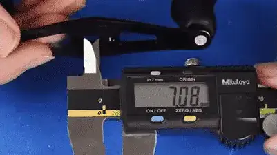
To make sure that your spinning reel handle has the right dimension and rule out confusion, use a digital caliper that works with 0.01 mm precision. Standard rulers might not be precise enough for micro tolerances during measurement—use a digital vernier caliper.
Point 1. Outer Diameter of the Shaft / Hex Width
In the case of screw-in shafts, measure the unthreaded portion of the drive shaft that fits inside the reel body.
For screw-in shafts:
- 4.00mm is the standard outer diameter for ultra-light reels in the 1000-3000 size range.
- 5.00mm is the standard outer diameter for reels which are 4000 and larger.
For hexagon through-shaft setups, place the caliper parallel to the flat sides to measure the diameter accurately instead of measuring corner-to-corner. Standard widths are usually 4.5mm or 5mm.
Point 2: Calculating Effective Shaft Length
You will also measure the total depth of insertion. It includes the distance from the base shoulder to the tip of the threaded rod or clip groove. This guarantees correct gear engagement without leaving excess space at the shoulder.
Point 3: Calculating Outer Diameter of Thread & Pitch
You must measure the outer diameter of the thread peaks with a caliper. This is followed by measuring the thread pitch using a pitch gauge (M4.5 x 0.75 type, or M5 x 0.8 type). Note that some double handle systems feature reverse threads on one side.

Step 3: Chart of Sizes of Spinning Reel Handles and Knobs
When cross-checking measurements against OEM standards or aftermarket options for a Shimano Handle Upgrade , use this technical compatibility table for your spinning reel handle shaft.
| Spinning Reel Type and Series | Sizes | Shaft Outer Diameter | Knob Shaft Diameter | Included Bearing Specs |
|---|---|---|---|---|
| Shimano Type A | 1000 – C3000/4000 (Freshwater) | 4.00mm (Screw-in/Hex) | 4.00mm | 4x7x2.5mm |
| Shimano Type B | SW 4000 – 30000 (Offshore) | 5.00mm | 5.00mm | 5x8x2.5mm / 5x9x3.0mm |
| Daiwa Type S | 1000 – 3000 (LT Series) | 4.00mm/5.00mm Step Shaft | 4.00mm | 4x7x2.5mm (Inner) / 4x7x2.0mm |
| Daiwa Type L | 3000 – 8000 (Saltwater) | 5.00mm | 5.00mm | 5x8x2.5mm (850ZZ) |
| Abu Garcia Standard | 1000 – 4000 (Revo / Roxani) | 4.00mm / 4.50mm (Screw-in/Hex) | 5.00mm | 5x8x2.5mm (850ZZ) |
| Abu Garcia Heavy Duty | 5000 – 8000 (Offshore / Inshore) | 5.00mm | 5.00mm | 5x8x2.5mm (850ZZ) |
| Penn Standard Series | 1000 – 5000 (Spinfisher / Battle) | 4.00mm (Screw-in/Hex) | 4.00mm | 4x7x2.5mm (740ZZ) |
| Penn Heavy Duty Series | 6000 – 10500 (Slammer / Authority) | 5.00mm | 5.00mm | 5x8x2.5mm (850ZZ) |
Step 4: A Zero-Play Spinning Reel Handle Installation Guide
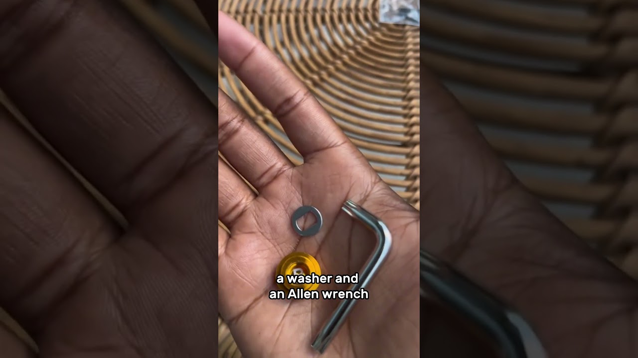
After finding out and selecting the needed handle or knob size, use the following sequence to install and adjust the shaft:
- Clean and Inspect: Wipe the drive shaft and gear opening with isopropyl alcohol. Dirt or old grease can affect fit tolerances, making them larger by 0.05 – 0.1mm.
- Aligning Gear Teeth Before Tightening: When inserting a new shaft, do not force it into position. If there is resistance, rotate the rotor with one hand while holding the shaft with the other until you find the position where gears align horizontally without force.
- Eliminating Axial Play with Micro Shims: Manufacturing defects can cause slight back-and-forth movement. Insert ultra-thin copper or stainless steel shims (0.05mm; 0.1mm; 0.2mm) in between until you achieve a smooth turn with zero axial movement.
- Prevent Backlash and Loosening: For screw-in models, ensure you Prepare Saltwater Tackle properly before offshore trips by applying a low-strength thread-locking agent (blue Loctite 222 type) on the shaft threads to prevent unwanted vibration or loosening.